Context:Final Project for Physical Computing @ NYU ITP (and how I got my job as a Physical Computing TA!)
Role: Arduino coder, problem solver, circuit designer, soldering jockey
Concept: Modular synthesizer sourced from instruments without any MIDI compatibilty (yes, we could have used MIDI, but that’s not the point)
Tools:
Arduino + a lot of wiring
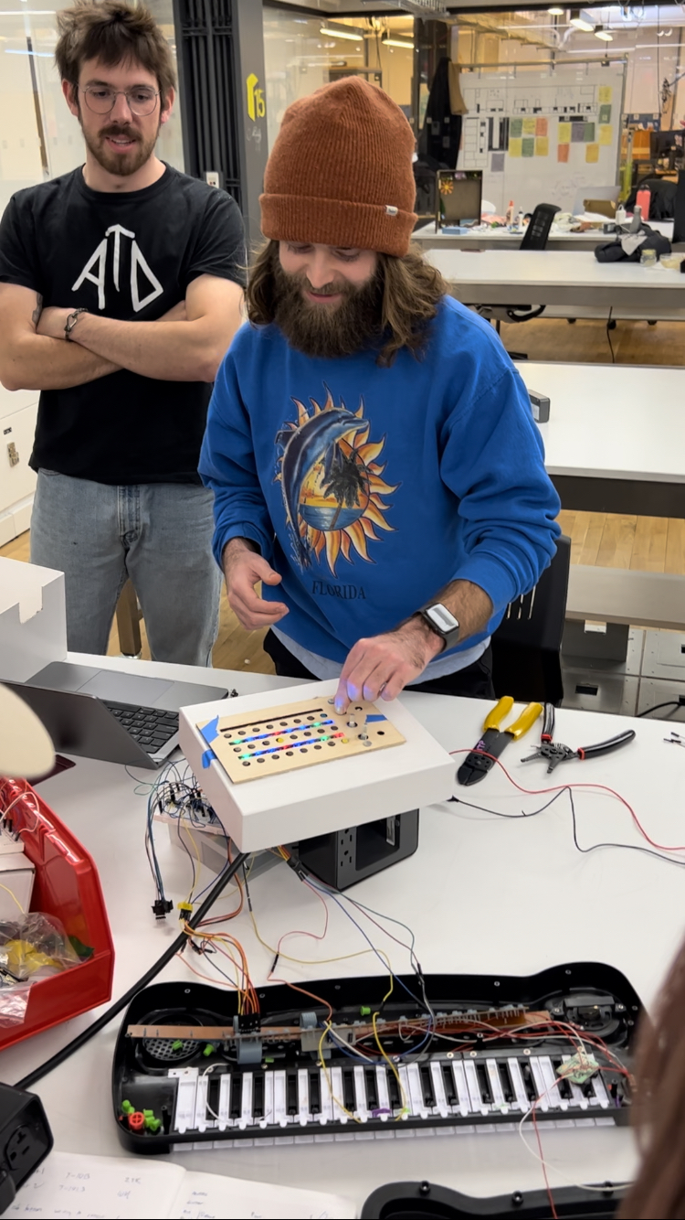
The Funkenstein
This project was a collaboration between myself and fellow ITP student Tres Pimentel. We were interested in exploring the potential of sequencing musical instruments that, in a typical context, simply could not be sequenced. We settled on using budget instruments from thrift shops that lacked a MIDI port, and essentially attempted to hack a sequencing functionality into the instruments using Arduino. We prototyped an interface for the instrument and developed a note-triggering protocol using multiplexer interactions.
Ideation
When Tres and I first met for the first time about this project, he had the idea to circuit-bend a children’s instrument, to create some cool sonic effects. I was also interested in this idea, but in the interest of trying to develop something that seemed to be completely undocumented online, I was also interested in developing a form of circuit-bending that would allow us to sequence the instrument as a form of circuit-bending. Because Tres wanted to circuit-bend multiple instruments and I wanted to sequence multiple instruments, we decided that we’d focus on both the sequencing and circuit-bending as we developed our instrument.First Steps
We started by collecting some children’s instruments. Tres picked up a children’s piano, congas, and guitar. Since he was able to easily find 3 children’s instruments, we decided it would be cool to have our little sequencer sequence 3 different things. This number is important - remember it for later.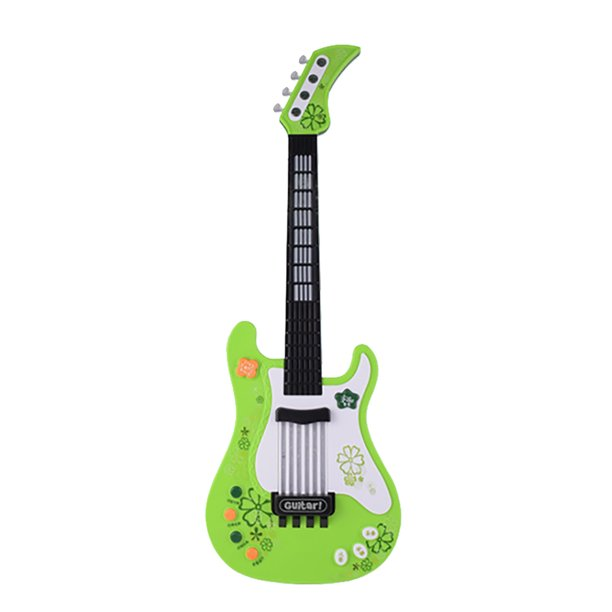

 these aren’t our exact instruments but they’re pretty close.
Second Steps
So, we had our three instruments and we had our idea - now we just had to figure out how to bridge the gap between them. The first thing to do was to figure out the best way to sequence these things. In a typical sequencer, there are two modes - a “write” mode, wherein notes are passed from the user into the instrument, and a “read” mode, where the instrument plays the user-specified notes at a fixed interval (typically adjustable on the fly). While other sequencers are capable of snazzier things, we thought a simplistic “read” and “write” mode would more than suffice for this project.After looking at some examples, both via YouTube videos and Arduino, we decided to essentially blend the ideas we discovered in an original way. However, it’s one thing to have nice implementational ideas, and a completely different thing to be able to execute on them, both on the hardware and software fronts. In order to actually do any of this stuff, we’d have to delve deep into the guts of our instruments and attempt to understand what made them tick.
Third Steps - Circuit Bending V0.1
In order to get the instruments to play notes without pressing the keys (the point of a sequencer), we had to figure out how notes were actually triggered in the instruments. This involved Tres (our project’s circuit-bending liaison) opening up all the instruments, and essentially touching a bunch of stuff together until sound was produced. Also, writing it down afterwards so we wouldn’t forget what pin combos produced what sounds! He started with the piano, and after a bit of time, had figured out how to play 4 octaves of notes. Nice! Now, to prove the viability of this concept, all we had to do was wire up some header pins to the sonorant pins and pass high signals to them to get notes whenever we wanted.
… Except of course it wasn’t that simple.
As we immediately figured out upon attempting the experiment above, sending high signals is not the same as touching two different pins together. Although it took a bit to figure out, the reason for this became clear: the piano, like the rest of our instruments, was independently powered, and rather than just needing a little bit of juice to play a note, used some esoteric circuit-routing passed into a sound card in order to trigger notes. That meant that instead of just sending some 1s and 0s and calling it a day, we had to route the independent circuit of the piano (and other instruments) between two sonorant pins in order to make a note to play. Now how the heck does someone do that?
Fourth Steps - Multiplexers
My immediate thought upon the failure of our experiment was to use some multiplexers. However, the concept seemed fanciful - would it really be so easy as just plugging all the pins into a multiplexer and routing between pins? Of course not, partly because that’s not how multiplexers even work. This problem stumped us for several days, and we were looking into a variety of different solutions until we encountered this example and this example - a mux/demux chain that used multiplexers! As you can read about in the spec if you’re interested, this implementation takes a voltage/signal from any of the 8 mux pins, routes it to a second multiplexer via COM I/O, and then routes it to any of the 8 demux pins based on its specified gate. This seemed like it actually could maybe work, provided we were very intentional about which pins on the piano went to which pins of the mux/demux.
FOURTH.1 STEPS - THIS IS HARD AND WE ARE BAD AT IT
you might think this implementation, with its two multiplexers, six gates, and 16 pins might sound a little convoluted. Turns out, it’s convoluted for a different set of reasons relating to how the multiplexer needs to handle voltage/be powered. Most notably, there’s a pin on multiplexers called the “inhibit” or “enable” pin, which, in order for the multiplexer to actually work, needs to be plugged in to ground. Ignore the charlatans online who falsely claim that you can run a LOW/HIGH signal to this to toggle it! This may actually work for some, but in our circuit, we spent multiple days just trying to figure out the grounding.
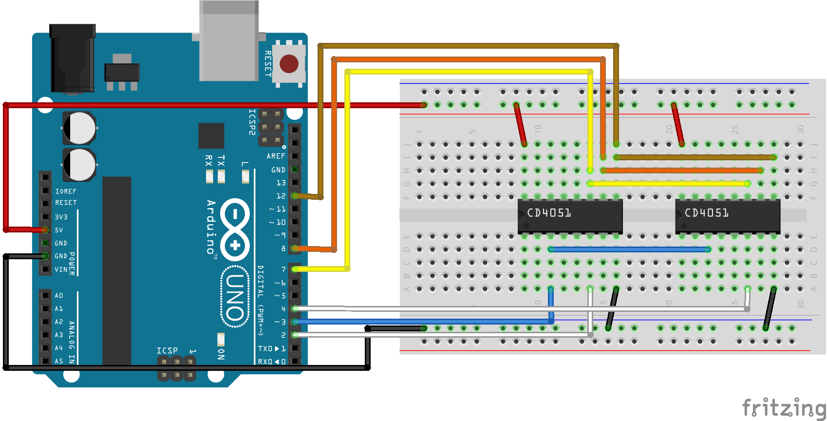
we scrutinized this image for hours without realizing that the circuit shown doesn’t work.
Once we figured out how the darn mux/demux thing worked, it was an extremely pleasant surprise to hear a note playing on our piano. How quaint! From this point, we were ready to start sequencing notes. But how can you sequence notes when you’re routing a signal? Turns out you need to sequence not the notes, but the routes which correspond to the notes. The challenge here is that we had 8 pins per mux, but we needed to figure out how to route a signal linearly to play 34 different notes on the piano. The solution to this problem, as usual, turned out to lie in binary.
int myArray[40][6]{ {0,0,0,0,0,0}, {0,0,0,0,0,1}, {0,0,0,0,1,0}, {0,0,0,0,1,1}, {0,0,0,1,0,0}, {0,0,0,1,0,1}, {0,0,0,1,1,0}, {0,0,0,1,1,1}, {0,0,1,0,0,0}, {0,0,1,0,0,1}, {0,0,1,0,1,0}, {0,0,1,0,1,1}, {0,0,1,1,0,0}, {0,0,1,1,0,1}, {0,0,1,1,1,1}, {0,1,0,0,0,0}, {0,1,0,0,0,1}, {0,1,0,0,1,0}, {0,1,0,0,1,1}, {0,1,0,1,0,0}, {0,1,0,1,0,1}, {0,1,0,1,1,1}, {0,1,1,0,0,0}, {0,1,1,0,0,1}, {0,1,1,0,1,0}, {0,1,1,0,1,1}, {0,1,1,1,0,0}, {0,1,1,1,0,1}, {0,1,1,1,1,0}, {0,1,1,1,1,1}, {1,0,0,0,0,0}, {1,0,0,0,0,1}, {1,0,0,0,1,0}, {1,0,0,0,1,1}, {1,0,0,1,0,0}, {1,0,0,1,0,1}, {1,0,0,1,1,0}, {1,0,0,1,1,1}, {1,0,1,0,0,0}, {1,0,1,0,0,1} };
This is the logic array that we ended up using to control our pins. This is just binary from 1 to 40, but we can use this to route 40 different signals from the Arduino with a little help from the logic gate below.
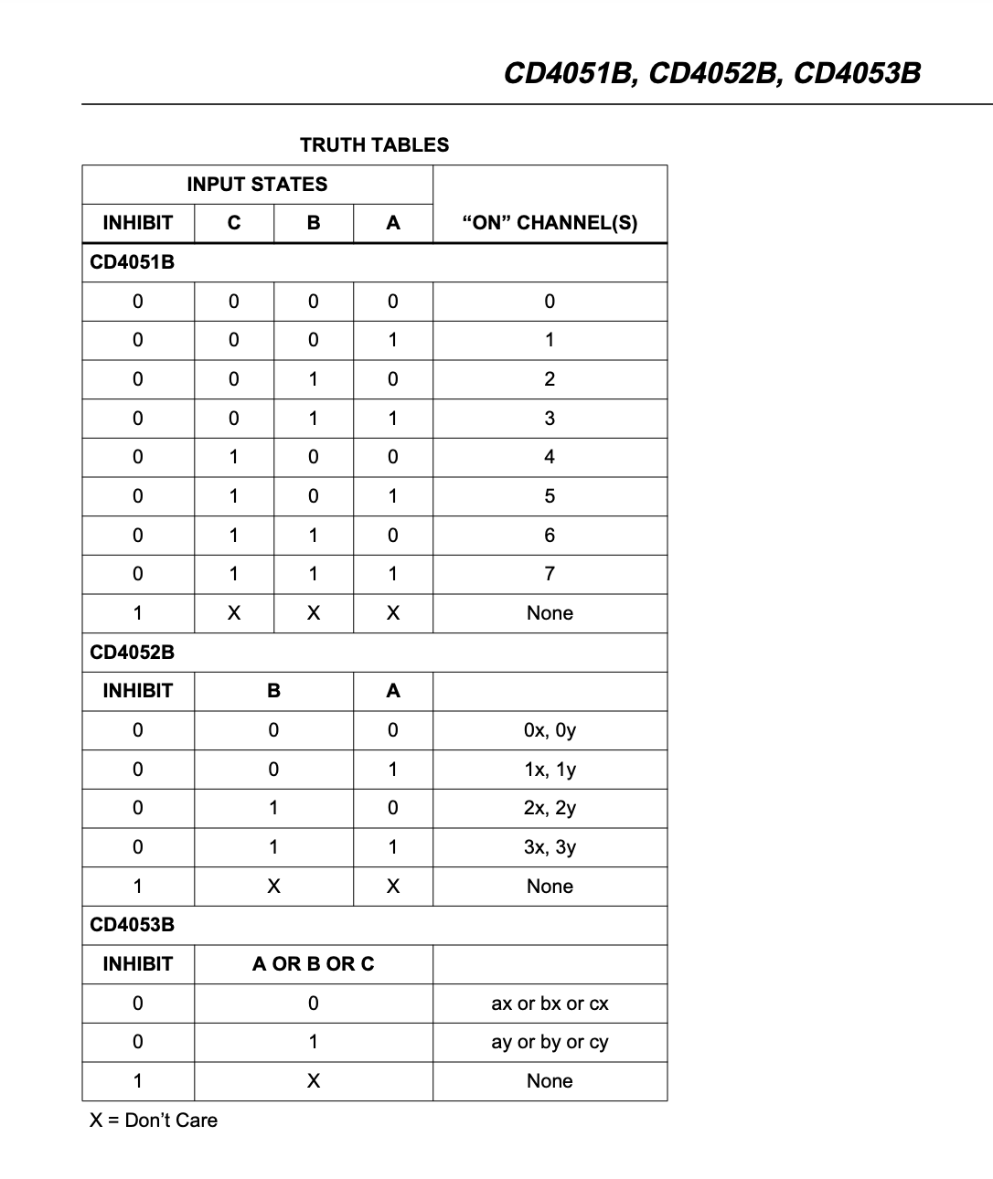
Basically, if you send the first 3 values of the 6-bit binary value to one of the muxes, and you send the other 3 bits to the other mux, you can get 40 different values. Pretty cool! To send these values appropriately, we split our 6-bit array into two different 3-bit numbers (1 through 8) that we sent to separate muxes. After a bunch of fiddling, this worked as intended, and we were able to get beautiful chromatic ascension out of our piano just by twisting a potentiometer.
Fifth Steps - Reading, ‘Riting, and ‘Rithmetic
Now that we could send any note sequence we wanted to the piano from the computer, we had to figure out 1) how to dynamically send values for the piano to play, 2) how to read those values back in a separate state, and 3) what the hardware interaction for such a thing would look like. We looked at the YouTube videos above and decided on the following interaction for the write mode:
while a button is held, its corresponding array value will be constantly overwritten by a potentiometer value.
Sounds easy enough, but proved to be tricky! Took a day or so to master this code. Next, we had to figure out read mode, which we defined with the following logic:
play back stored notes at a given time interval delay.
This turned out to be pretty easy, at least the way we did it. There’s another (better) way to implement this to make it more dynamic, but we chose to code it the less cool way instead because we like to make life harder for ourselves.
Sixth Steps - Extrapolation (Cathexis)
So, at this stage, we had one instrument running really well (out of the 3 intended), and it seemed like our read/write code was working pretty good too. How hard could it be, we foolishly thought, to take what we’d figured out for one instrument and extrapolate out to 3? Turns out, it’s VERY HARD. For a VARIETY OF REASONS.
Problem 1: Buttons.
Our implementation used 8 buttons. That means 8 digital pins used. Not too bad, right? Unfortunately, with 3 instruments, we’d have to use 24 buttons. That meant that an Arduino Nano (which we’d been using) wasn’t gonna cut it. We went and got an Arduino Mega, but trying to use this raised an entirely new set of problems: even with 60 digital pins, a fully classically rigged set of 24 buttons would require at least 72 pins in the breadboard (power, ground, and signal), and although the Mega could handle that, Tres and I simply couldn’t. It didn’t help that our button board looked so chaotic once it was fabricated:
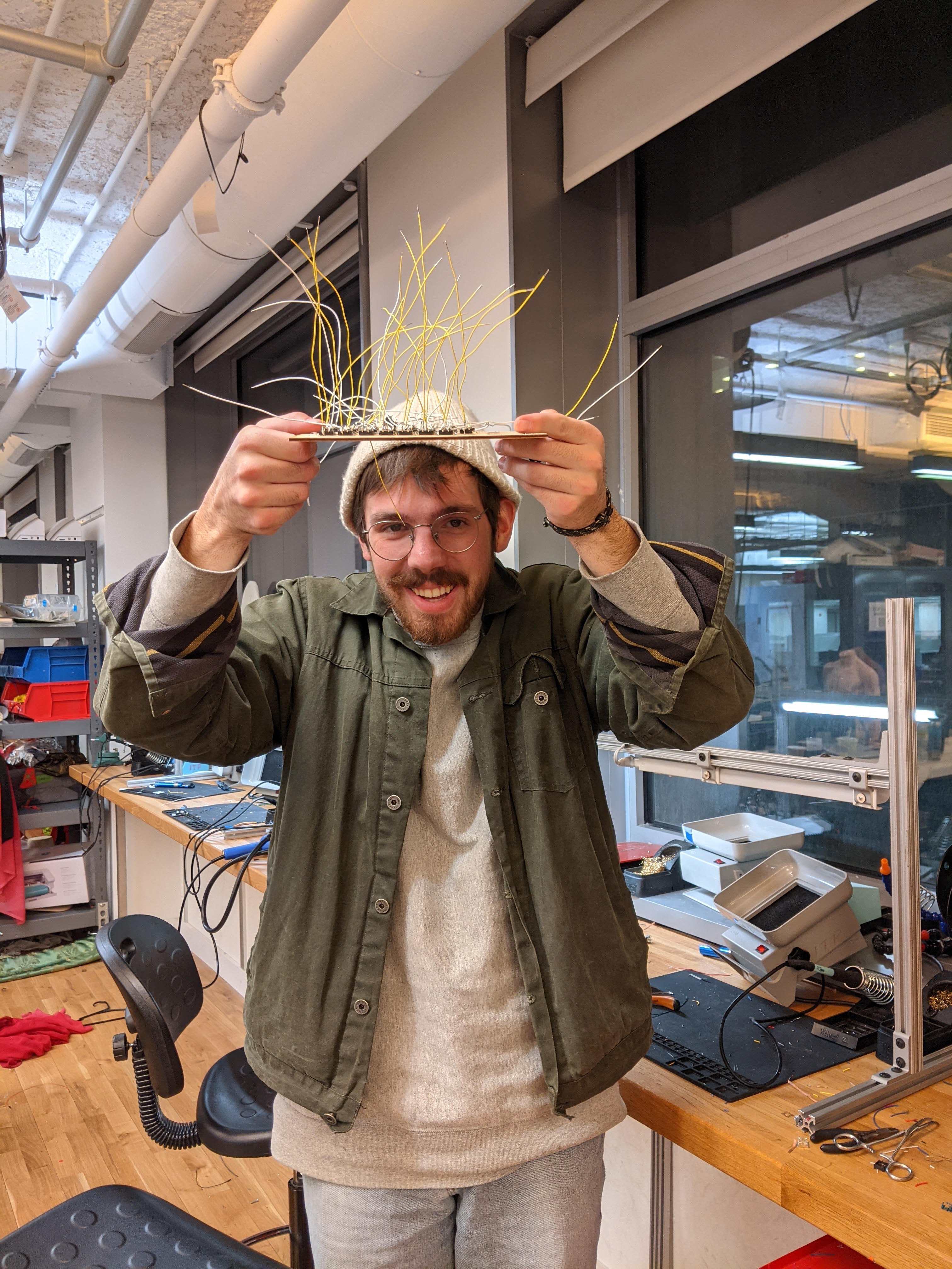 Look at this thing! It looks like spaghetti.
Faced with this nightmare of fabrication, we were forced to pivot: how could we read all these buttons without all the pins? The answer lay in Physical Computing, Ch. 14: row-column scanning.
SIXTH STEPS.1 - WHAT IS ROW COLUMN SCANNING AND HOW DO WE DO IT
Row-column scanning is a very valuable and resource-efficient method of reading a 2D array of sensors (buttons, pots, you name it) without needing to power and ground each one. It works wonders for things like, say, 24 buttons on a board, but diagrams for it also look a bit obtuse. Essentially, you wire together all the power pins and ground pins of your sensor, and pass them into the digital pins of whatever you’re working with. Although not shown in this diagram, some diodes on your rows can ensure no shorting occurs. This is quite fun to solder!
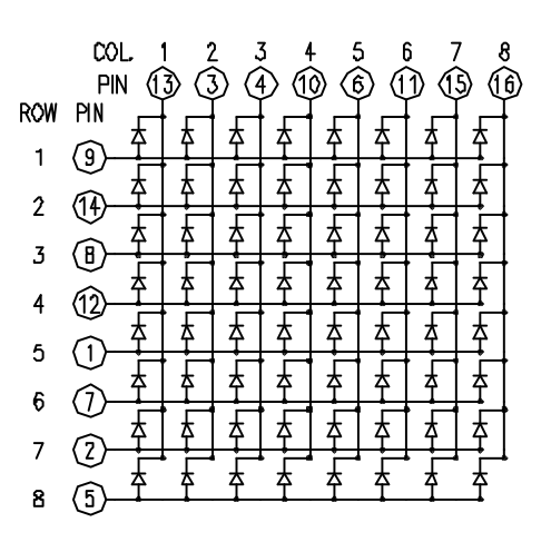
one of the classic row-col scan diagrams that are very simple, yet somehow confusing
We eventually figured this out with significant assistance from Xinyi (thank you!) and, after days of soldering, fooling around, and breaking things, finally got the darn circuit to work. However, this was only the first of our issues.
Problem 2: We are not good at soldering, and it is very hard to successfully solder these instruments.
When we modified our piano to support external meddling, all we had to do was solder some header pins onto some already existing header pins. This was not terribly difficult. However, for our subsequent instruments, our soldering was much trickier. For example, on our toy guitar, our solder joints looked like this:
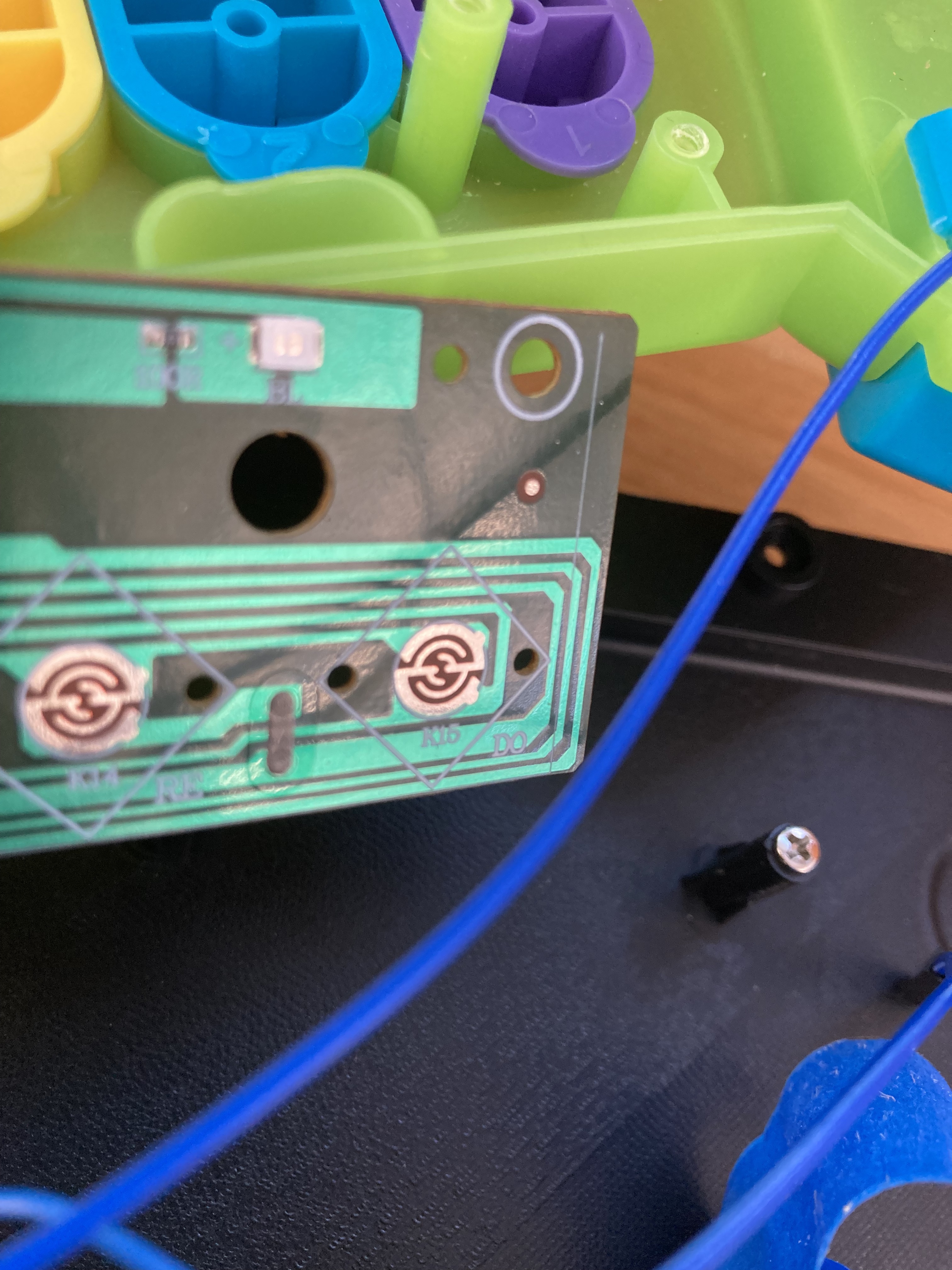
If your header pin touches the light green or the other copper shape, the whole thing shorts. Maybe not much of a challenge to an experienced fabricator, but for soldering newbies like myself, trying to get header pins on something like that proved to be a nightmare. Every solder job we did (even those we had done by fab shop members or experienced solderers) snapped off in a matter of hours, continually bogging down our progress and causing frustration/consternation. It actually continued to break up until the time of this writing!
Seventh Steps: Scaling + Fabrication (Catharsis)
After dealing with all of this junk for like a week and change, Tres and I found ourselves with only a few days left to complete the project and a veritable mountain of progress still to be made. This did not bode well, so we sat down and had a hard conversation - could we really make this happen with 3 different instruments? The answer that we came to was that, although we’d love to have the full implementation, we should move forward with what we had. At this stage of the game, that was a single instrument- the piano. With heavy hearts, we decided to move forward with just a singular instrument and try to have a nice working demo when we needed it. Because we had figured out the hard steps of mux/demux pairing and row-column scanning, we figured we could just chuck it in a box, throw on some glue and call it a day.
… Except of course it wasn’t that simple.
One Achilles heel we had was that neither of us are actually capable of good fabrication (at least, at the time we had to fabricate this thing). What should have been a 2-hour fun excursion turned into a 32-hour nonstop slogfest. I’ll spare most of the details, except that it couldn’t have been completed without the patience and expertise of Sam De Armas (you are the bomb dot com!). Then we debugged for many more hours, then I slept a little, and then we presented, and then I slept more. Here’s a photo/video dump with images/videos from development.
late-night debugging (warning: strong language)
The potentiometer runs!
about 100 hours in.
Big Josh impromptu freestyle.
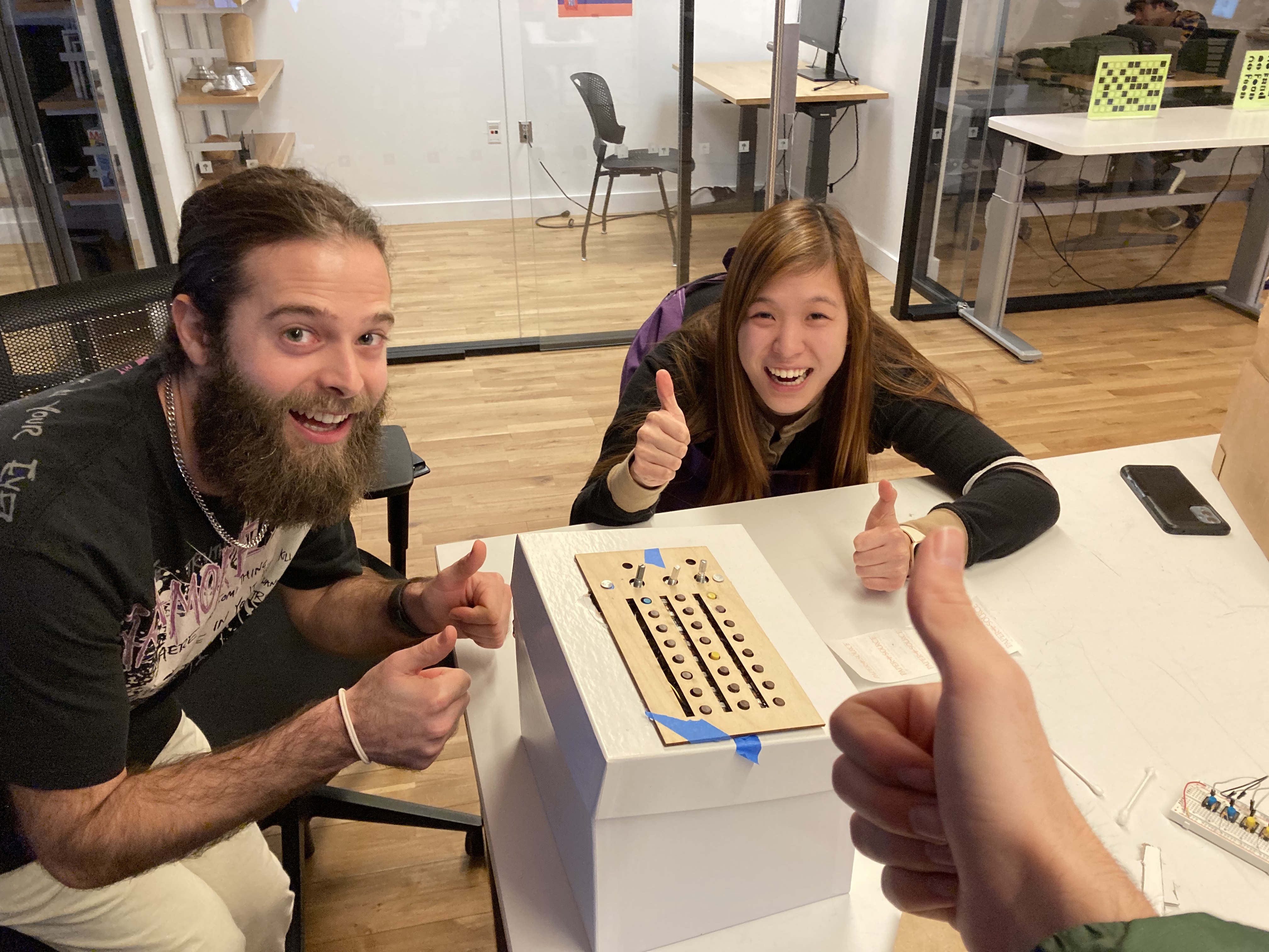 It’s in the box! Amazing.
SEVENTH STEPS.1 - CODING IS HARD AND WE ARE GOOD AT IT
You wanna know how we made this happen? You wanna make one of these too? Well, you’re in luck. I’m feeling magnanimous, so I’ll link you all the libraries we used - Keypad.h for our row-col scanning, and Adafruit_Neopixel.h to get our LEDs to run. Everything else was done with good old-fashioned elbow grease. Here’s how we ran the whole thing:
Yeah, it’s pretty long. Wanna know why? Cause we worked hard on it. Also, you may notice we’re using more pins than your standard Arduino - that’s because we picked up an Inland Mega 2560 from Micro Center to run it all.
N+1 Steps: The Future of the Project + Demos
Now that we’ve had a chance to present this mess, the question remains: what’s next? What is going on? What essentially happened is that we burnt ourselves out trying to work on this stuff, lost interest, and have tabled finishing the project for the entire semester. Bummer! While the video documentation is not great, I’d love to talk more about the project and I hope this article gives you an idea of my developmental process, interests, and personality. I really look forward to sharing more professional documentation of the final product with all of you.